Building an Ozeki NG SMS Gateway cluster on Windows Server 2012 R2
This guide gives information about how to build an Ozeki NG SMS Gateway cluster on Windows Server 2012 R2. In this text a failover cluster is discussed which can be used to prepare for hardware failures. If you setup a failover cluster your system will provide better uptimes and better tolerance against hardware related errors.
Update: If you provide SMPP SMS Service, we recommend you to use the SMPP Server and SMPP Client implementations offered by Ozeki 10 SMS gateway, with Ozeki Cluster over Ozeki NG, because they provide higher message throughput.
Before we begin the configuration of Ozeki NG cluster using Microsoft Windows Server 2012 R2, I will show you our own Ozeki Cluster software product which allows you to setup a cluster configuration easier than using Microsoft's solution.
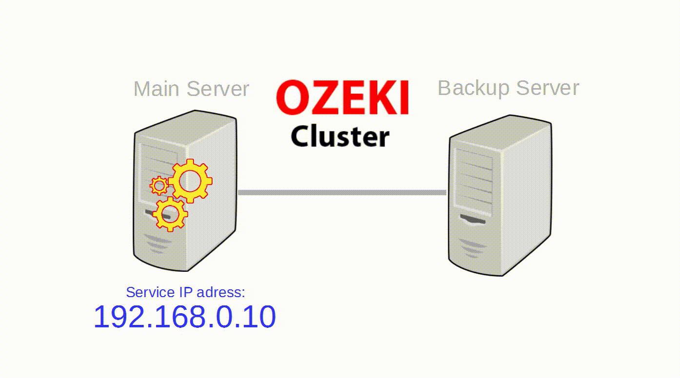
Ozeki Cluster is responsible for protecting your service against hardware failure and reach higher availability of your Ozeki NG SMS Gateway software. Ozeki Cluster automatically moves any service to another computer in case of a hardware failure. You can download it from the following website: ozekisms.com/index.php?owpn=1086
In the following part of this guide you will show how to configure your Windows Server 2012 R2.
The failover clustering will be working in the following way:
- The Ozeki NG SMS Gateway service will be running on one PC at the same time.
- The shared storage can be seen by only one computer at the same time (where the service is running).
- If the service will fail due to any reason, it will be restarted immediately on the same PC. If the service will be restarted as many times as it was provided, in the specified period (for example 5 times in 15 minutes), it will be restarted on the other PC after the next failure.
- If the computer will shutdown or there is a network failure, the service will be restarted on the other PC.
In order to setup failover clustering, you need the followings:
- Three Windows Server 2012 R2 operating systems on three computers.
- On one computer, an iSCSI virtual disk will be created.
- The two other computers will be connected to the virtual disk using iSCSI Initiator and the two Ozeki NG SMS Gateway will be installed on the virtual disk.
- Connect the two PCs to the same domain (without installing active directory). After you have connected the PCs to the domain, you need to login to your Windows operating systems using a domain user who is the member of the Domain Admins group. If you do not want to use a domain admin user, follow the instructions on the next page: https://technet.microsoft.com/en-us/library/cc731002(v=ws.10).aspx.
In the next part of the guide you can get information about the followings:
II. Performing basic settings on the two nodes
III. Connecting the two nodes to the same domain
IV. Connecting the two nodes to the virtual disk using iSCSI Initiator
V. Installing Ozeki NG SMS Gateway on the nodes
VI. Adding Failover Clustering role to the nodes
VII. Validating and creating a new failover cluster
VIII. Adding Ozeki NG SMS Gateway to the cluster
IX. Testing the cluster
I. Creating an iSCSI Virtual Disk on a remote Windows Server 2012 R2
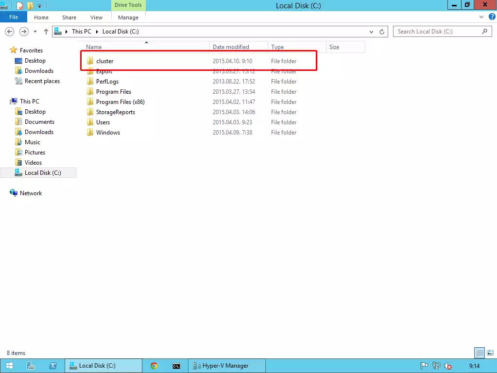
First, create a new folder where the virtual disk will be stored.
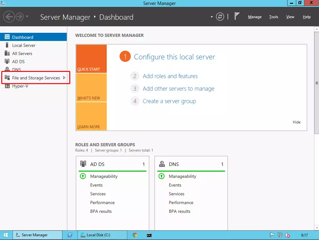
Under Server Manager, select File and Storage Services.
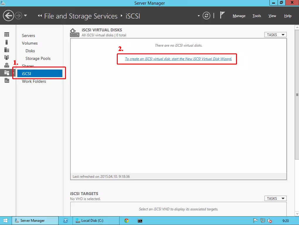
On the next page select iSCSI, and start the iSCSI Virtual Disk Wizard to create a new virtual disk that will be used by the two nodes. The two Ozeki NG SMS Gateway software products will be installed on this virtual disk.
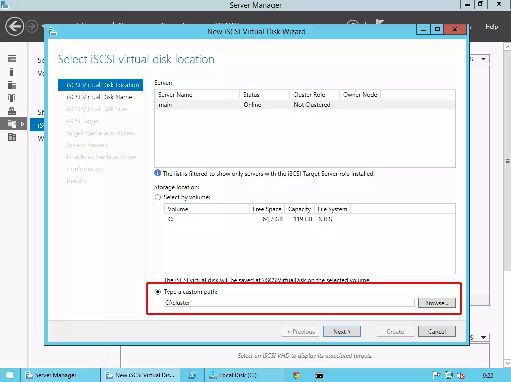
In the next window, select the "Type a custom path", and provide the previously created folder.
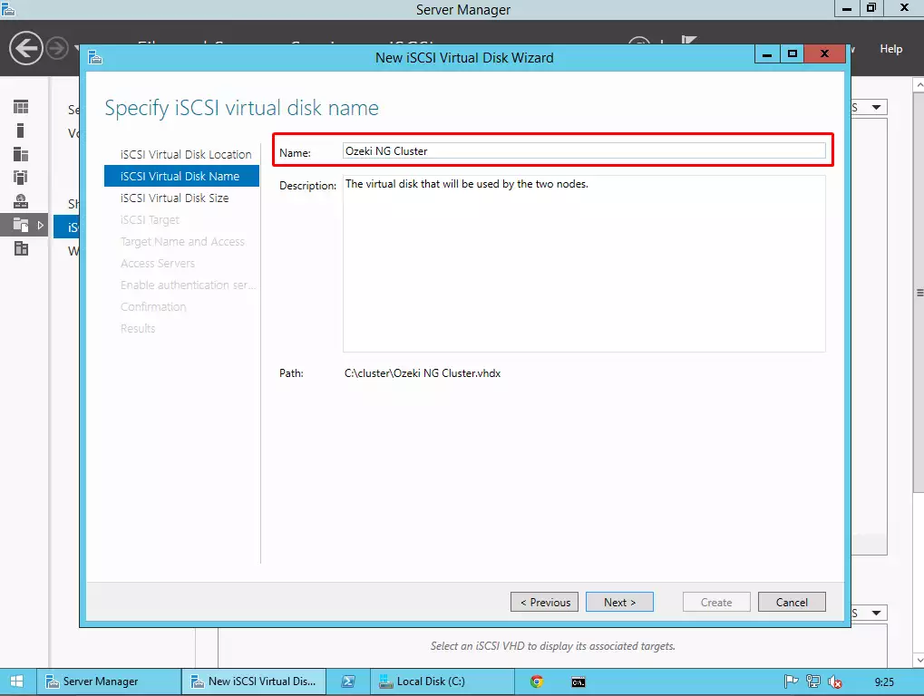
Then provide a name for the Virtual Disk.
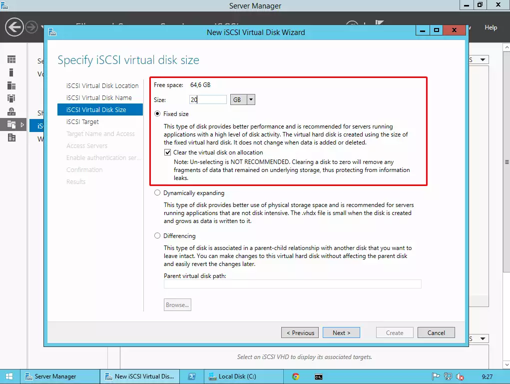
The next step is to determine the size of the virtual disk. Type a value (for the size) that you would like to use, and select Fixed size radio button.
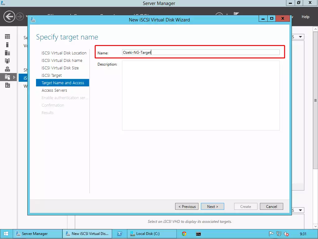
Now you should specify a target name for the two nodes.
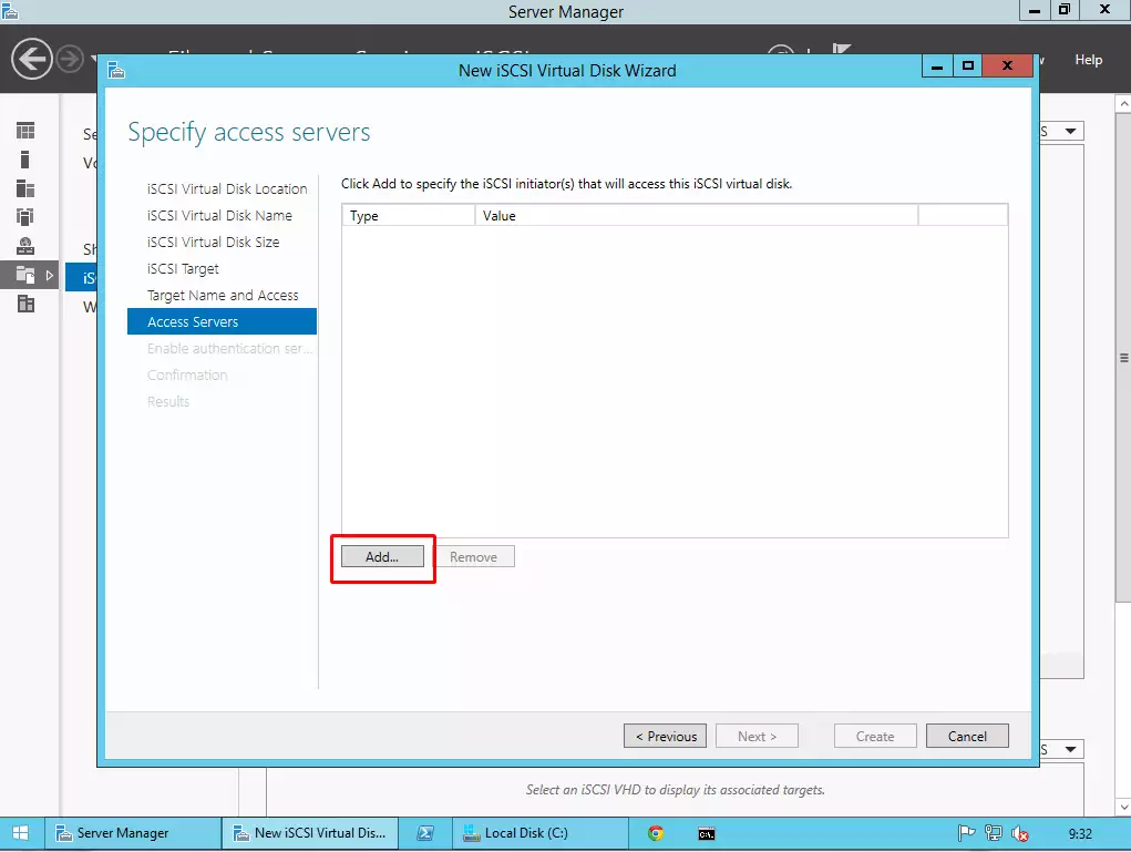
Now you need to specify the IP addresses of your two nodes to access the virtual disk.
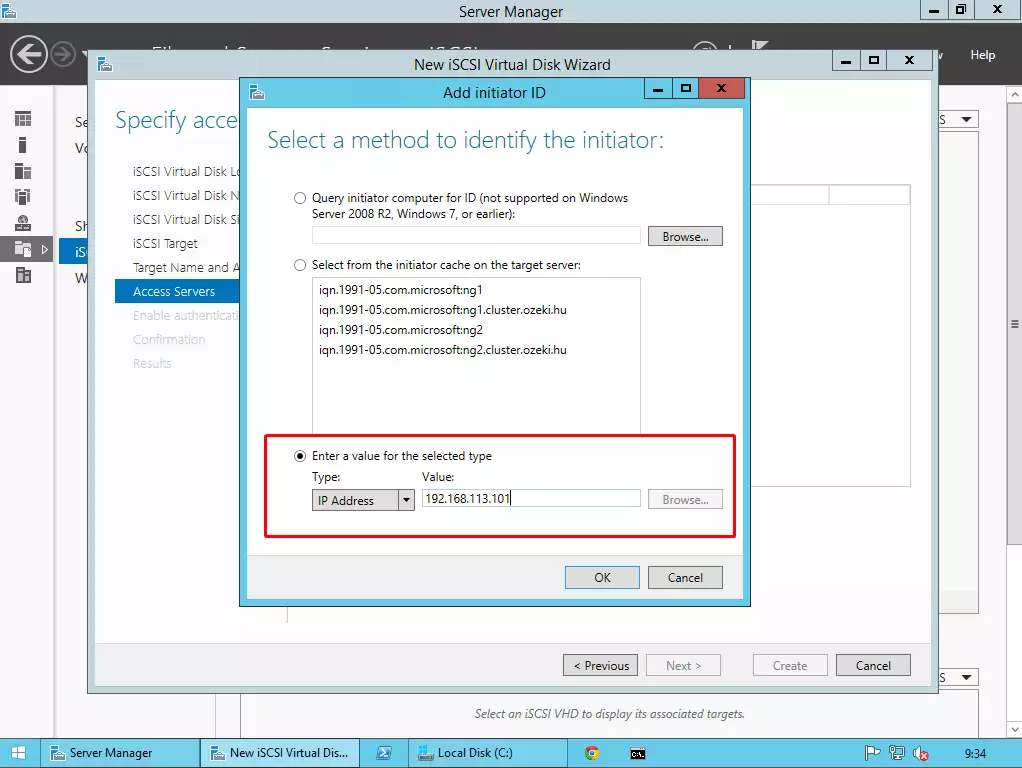
Select the last radio button and an IP address type. Then provide the ip address of your Node 1. After that perform this action again to give access to Node 2 as well.
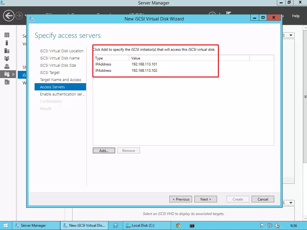
If you have added the two nodes, click on Next button.
If you would like to setup authentication, you can choose from chap or pap on the next page. If you do not want to set it up, just leave it blank, and click on next button. At the end of the process, click on Create button.
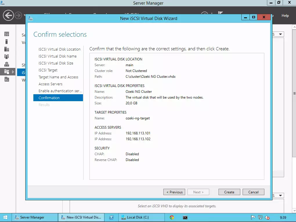
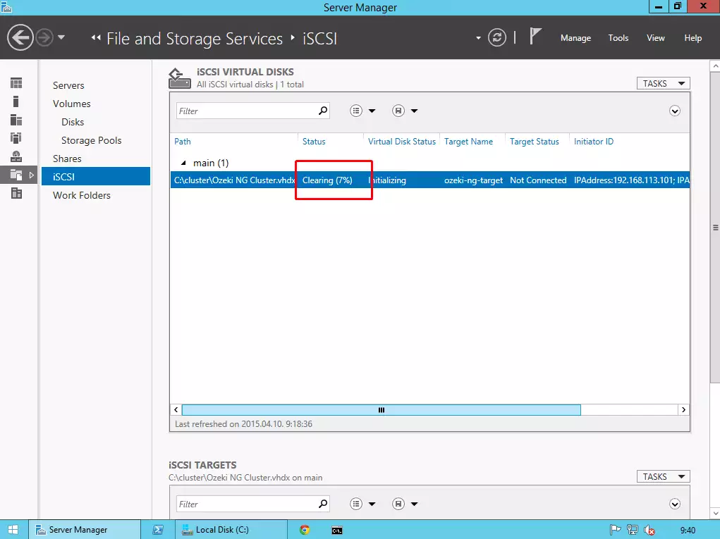
Then wait for the end of the process while Windows is creating and clearing the virtual disk.
II. Performing basic settings on the two nodes
Now, login to your two computers that will be the members of the cluster. In this guide I am using two freshly installed Windows Server 2012 R2 without any modifications, features or roles.
In this step you need to perform the following:
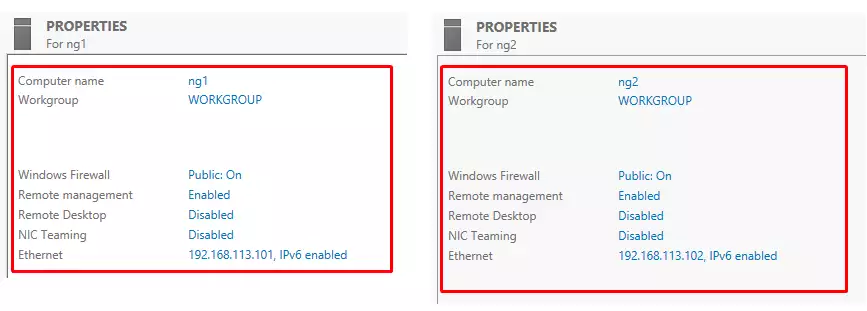
- Provide a static IPv4 address to your network interfaces
- Give a unique name for the PCs (e.g. ng1 and ng2)
III. Connecting the two nodes to the same domain
Now you need to connect the two computers to the same domain.
First click on WORKGROUP button on both PCs in the Server Manager \ Local Server menu.

Then click on the Change button to change the membership of the operating systems. Select Member of Domain and provide the domain name to where you would like to connect the two computers.
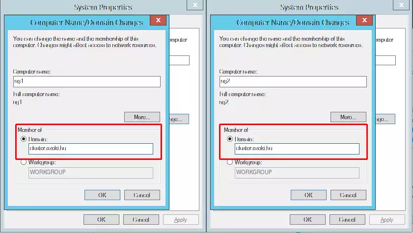
After that provide the name and the password of the Administrator on the domain and restart the two computers.
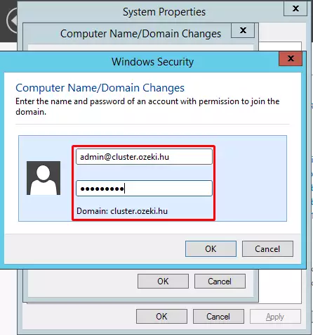
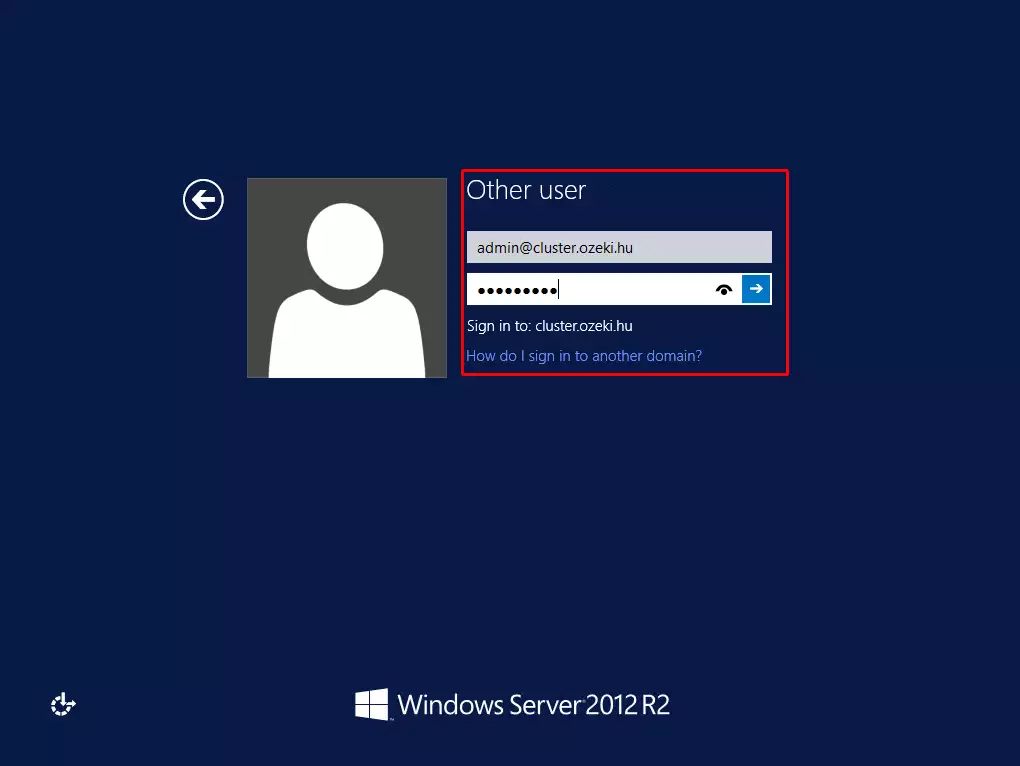
Then login to the two PCs with the admin user of the domain where you have connected the two PCs.
IV. Connecting the two nodes to the virtual disk using iSCSI Initiator
Now you need to connect the two nodes to the virtual disk that has been created earlier. You need to perform the following steps in both computers.
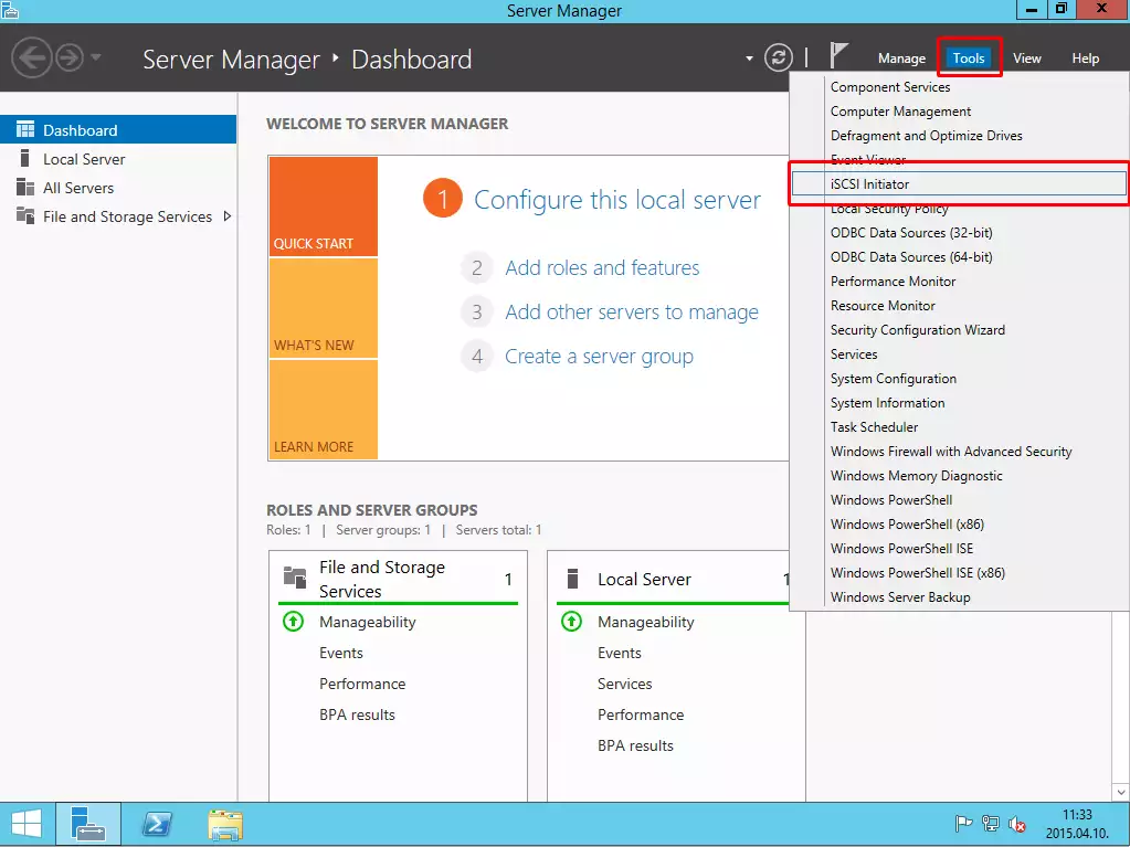
Click on Tools button, and select iSCSI Initiator from the list.
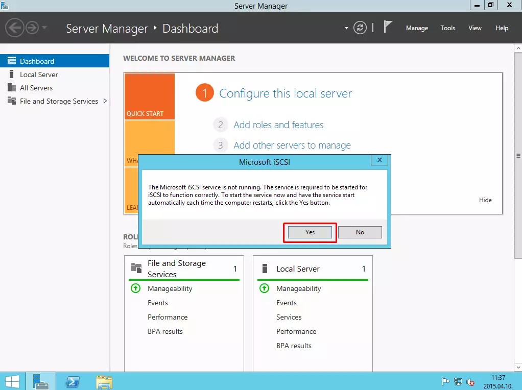
If the service is not running, click on Yes button.
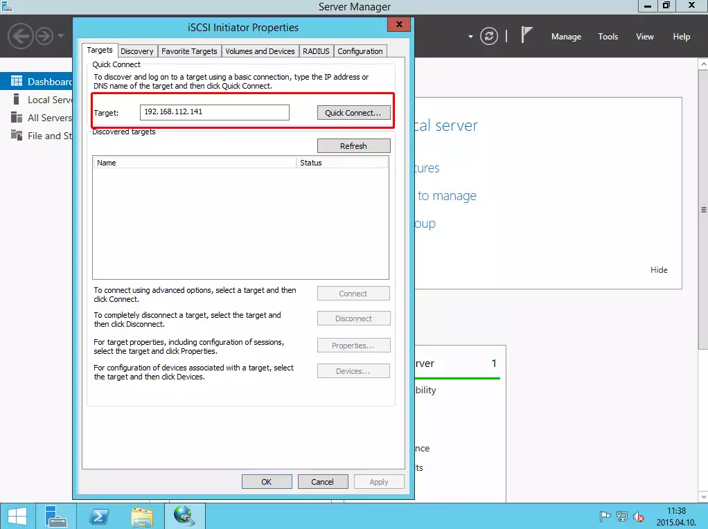
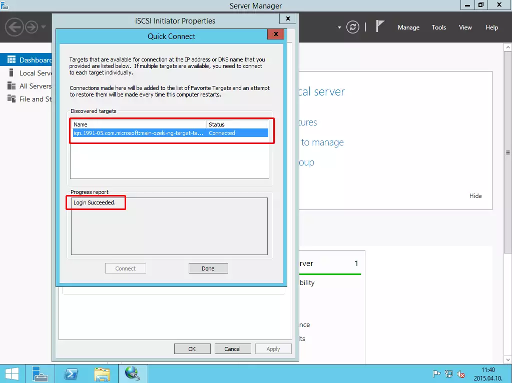
In the target textbox provide the IP address of the iSCSI virtual disk, and click on QuickConnect.
On the next window, you can see that the two computers connected to the virtual disk on the target server successfully.
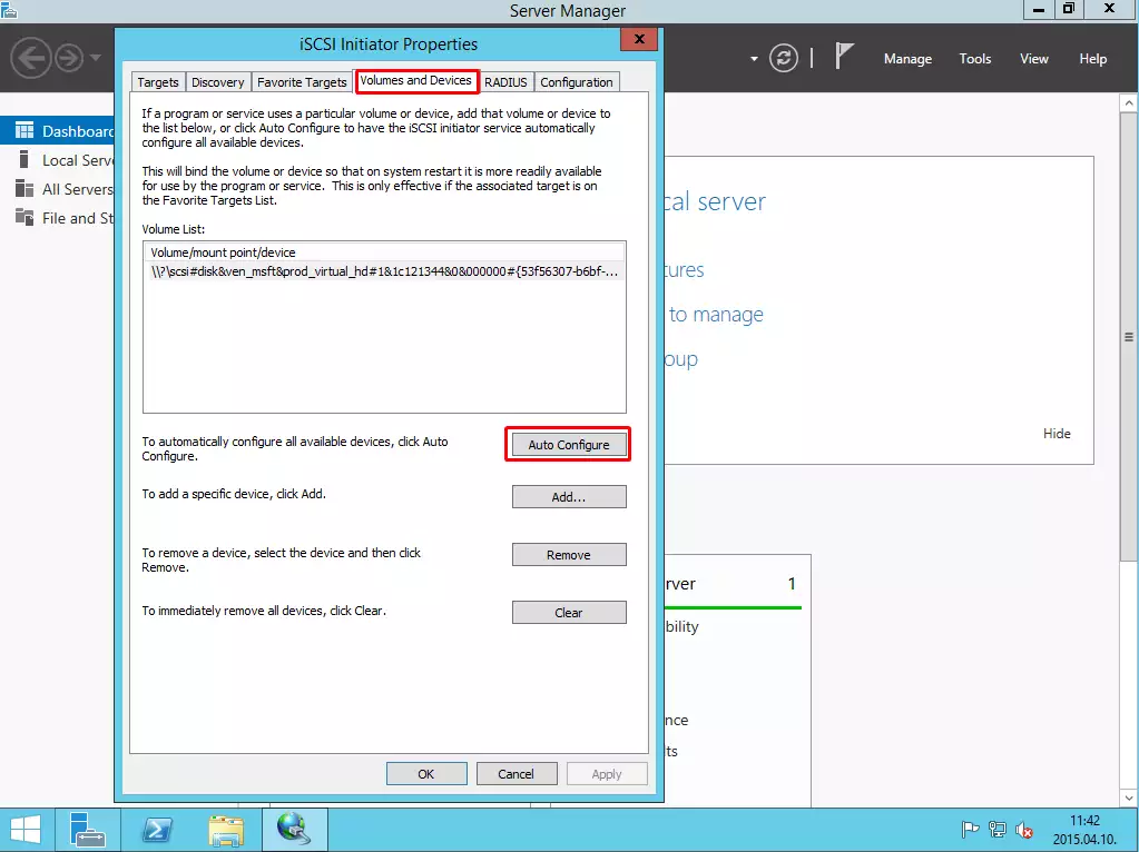
Under the Volumes and Devices tab click on Auto-configure.
As I said, the previous 5 steps have to be performed on the other PC, as well. The following steps have to be performed only on one PC.
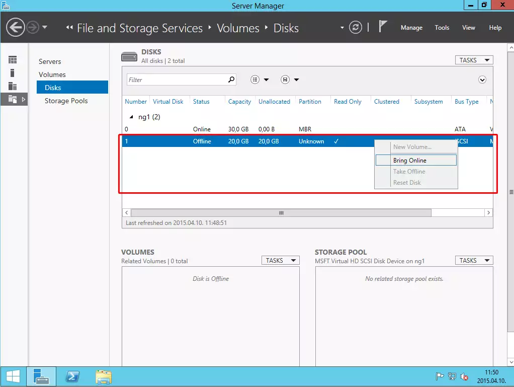
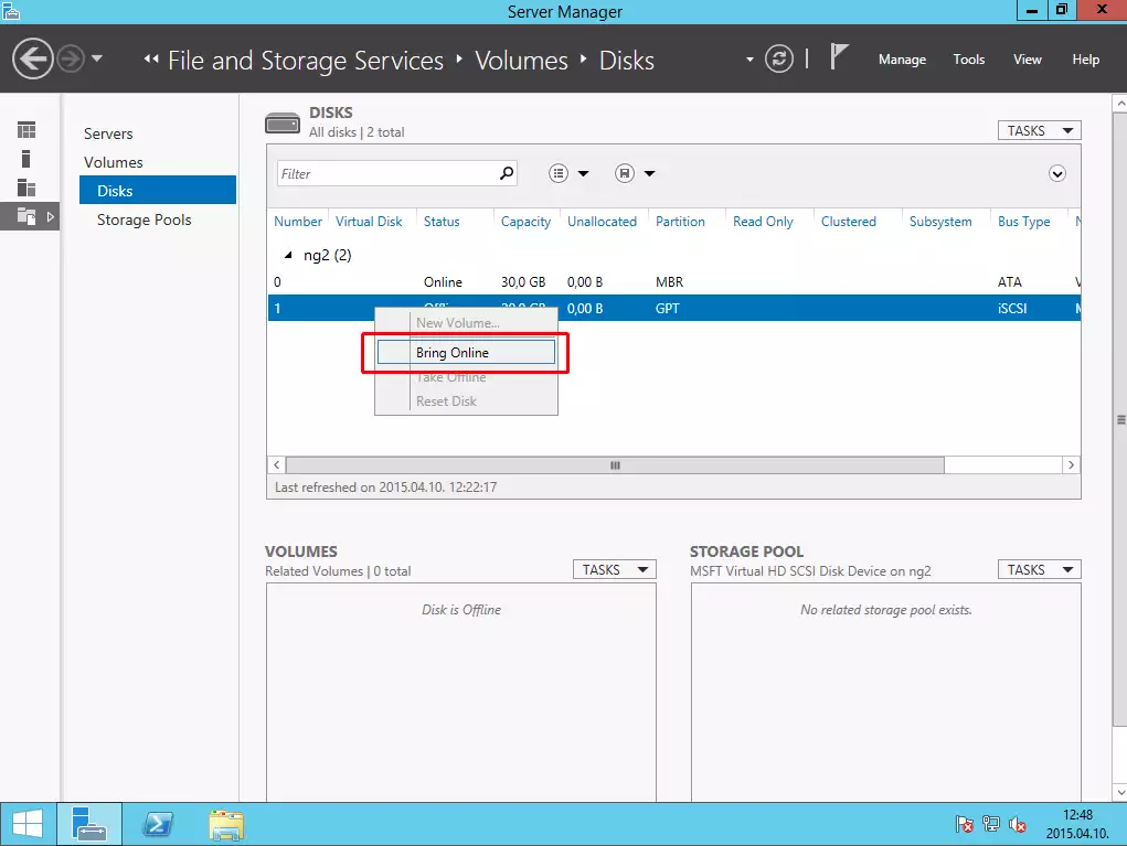
Under the Server Manager \ File and Storage Services, click on Disks and bring the virtual disk online.
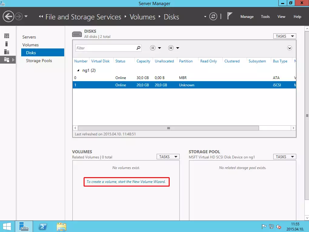
Then click on "To create a volume, start the new Volume wizard".
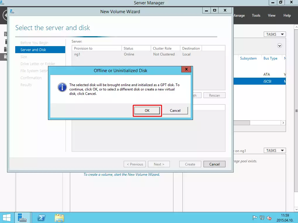
After that click on the OK button.
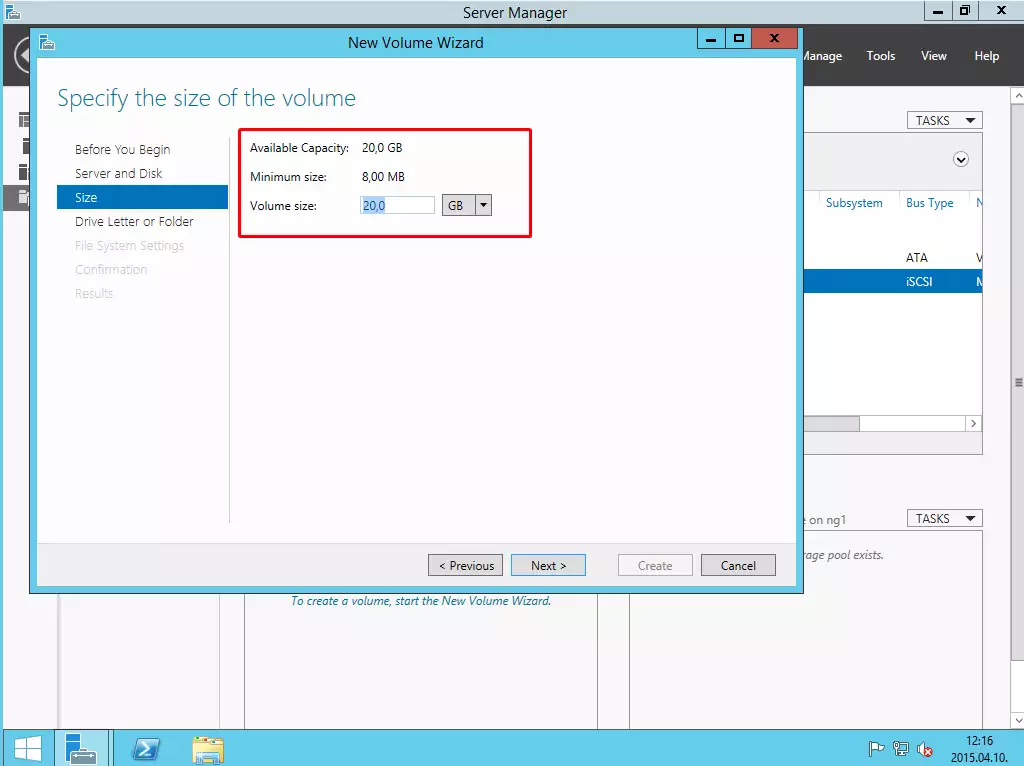
The next step is to specify the size of the volume.
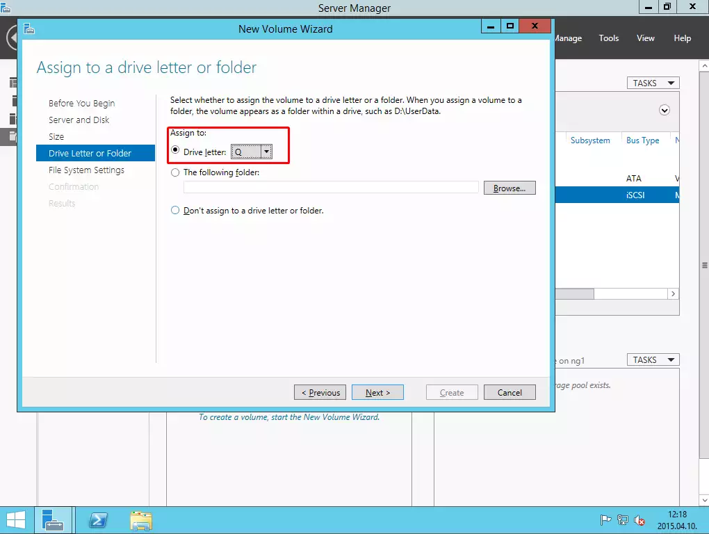
Now you need to specify the letter for the volume.
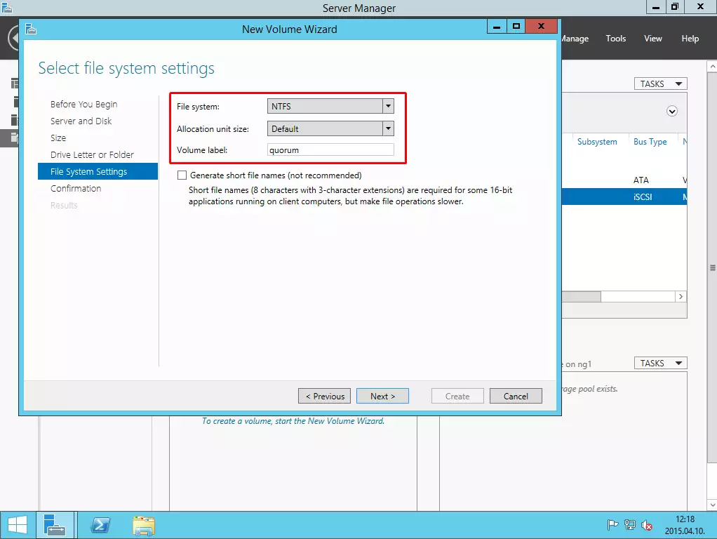
The next step is to select NTFS type of the partition and provide a label.
Finally, click on Create button and then you can see that the volume has been created.
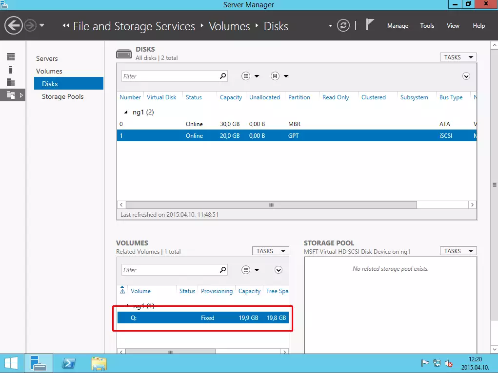
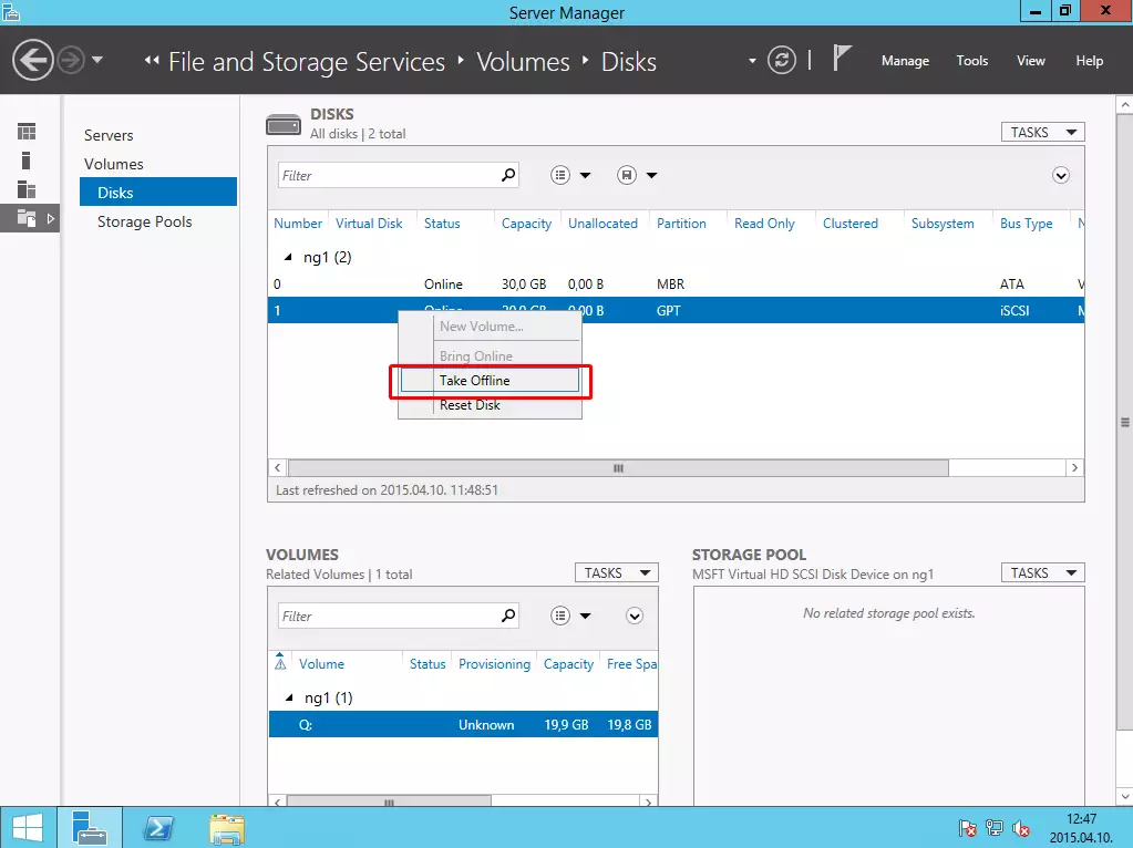
Take the disk offline, to be able to configure it on the other PC.
On the other PC take it online.
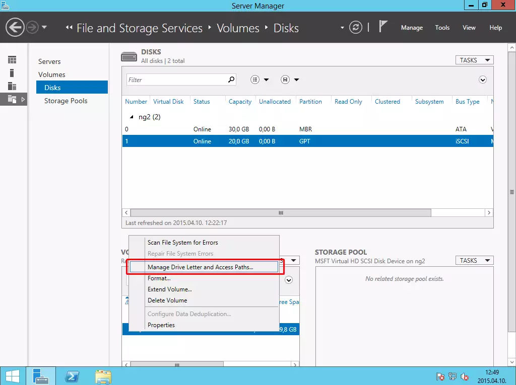
Finally take offline again, and return to the first Node.
V. Installing Ozeki NG SMS Gateway on the nodes
If the disk is active on the Node 1 (do not forget to take it offline on Node 2!) install the Ozeki NG SMS Gateway to Node 1 first, then on Node 2 (to install it on Node 2, first take it offline on Node 1, and take it online on Node 2).
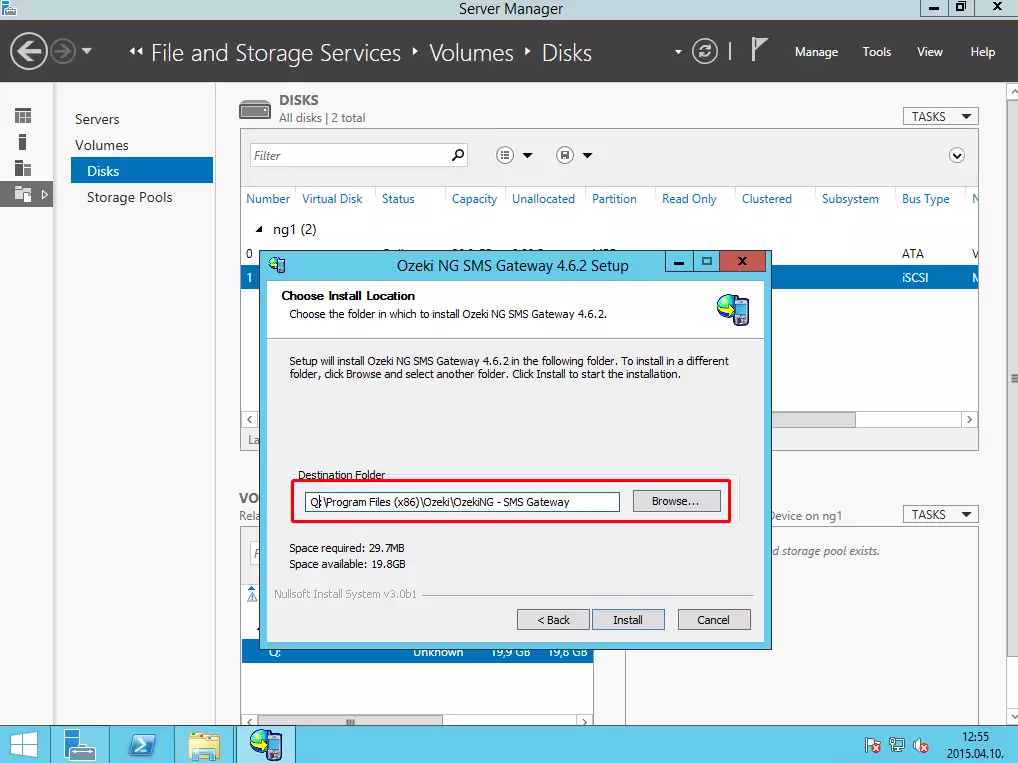
During the installation process, you need to change the installation path to Q drive.
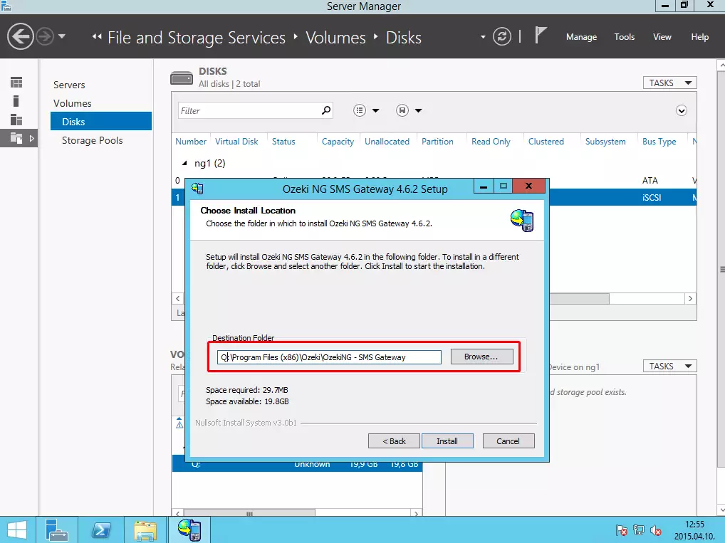
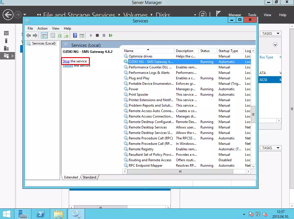
Now Stop the Ozeki NG service on Node 1.
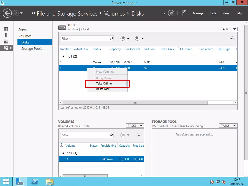
Then take the Disk offline again on Node 1.
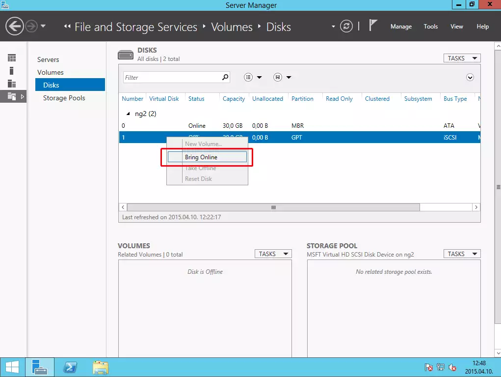
And take it Online on Node 2.
Then install the Ozeki NG SMS Gateway on Node 2 to the same directory on drive Q.
VI. Adding Failover Clustering role to the nodes
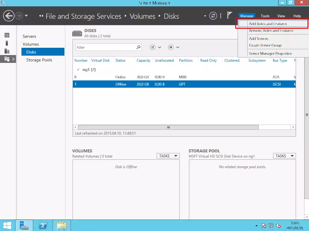
The next step is to add the Failover Clustering role to your two Windows Server 2012 R2 operating systems.
Click on Manage and Add Roles and Features.
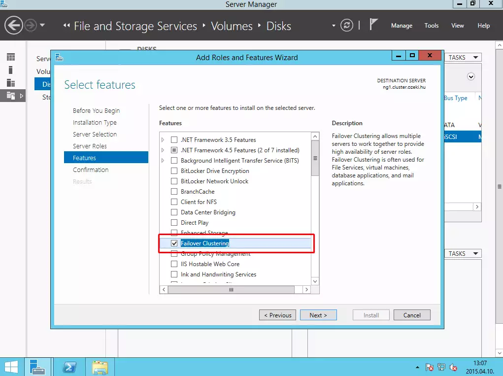
Under the Features list, select Failover clustering (on both Nodes) and click on Next button and then on Install button.
VII. Validating and creating a new failover cluster
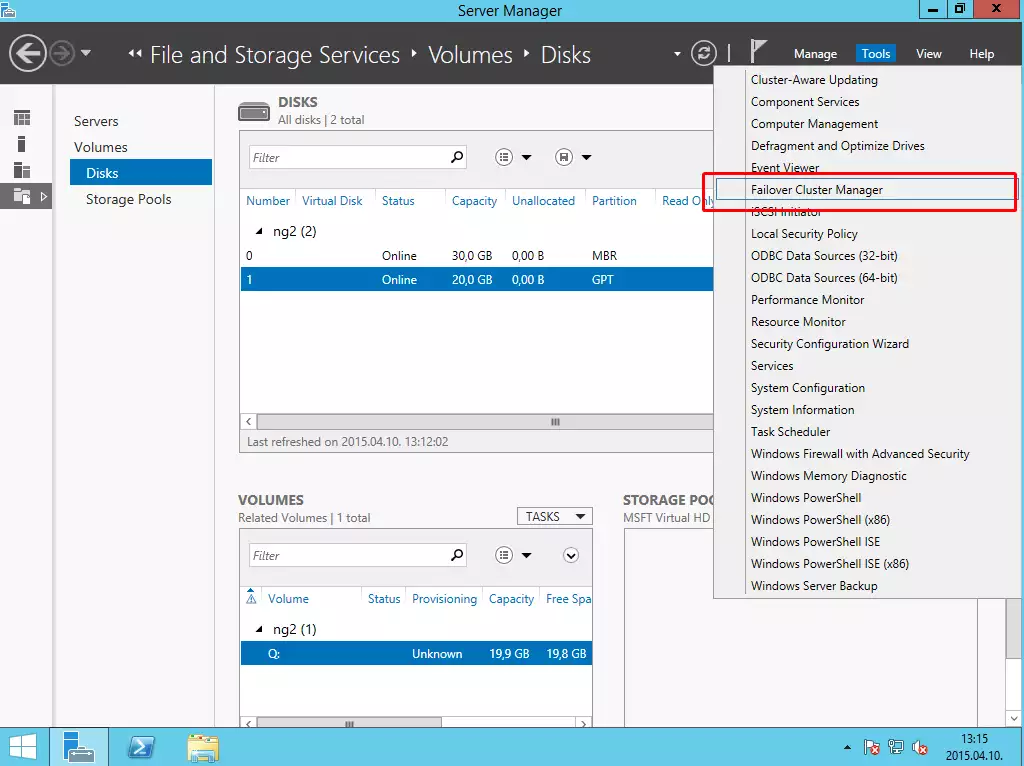
After you have installed the Ozeki NG SMS Gateway software product on both Nodes and added failover clustering role to your servers please open Failover Cluster Manager from the Tools menu.
Open it on that PC, where the shared disk is online at that moment.
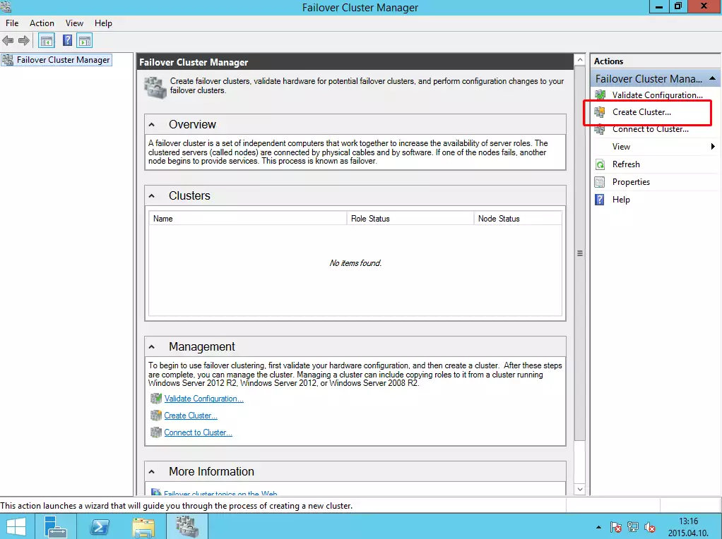
Click on Create button to create a new cluster.
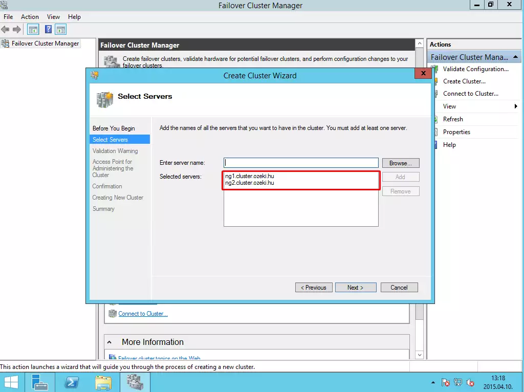
The next step is to specify the servers where you would like to use this cluster.
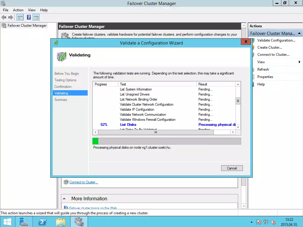
On the next page, the wizard can ask you to run the validation wizard. Click on Next button, and select Run all tests option. Let it finish the validation test.
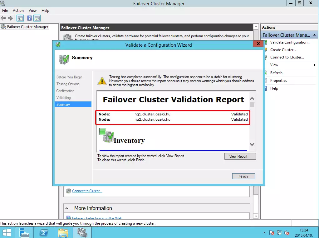
If the test has completed successfully (it means there is no error), click on Finish button to create your cluster.
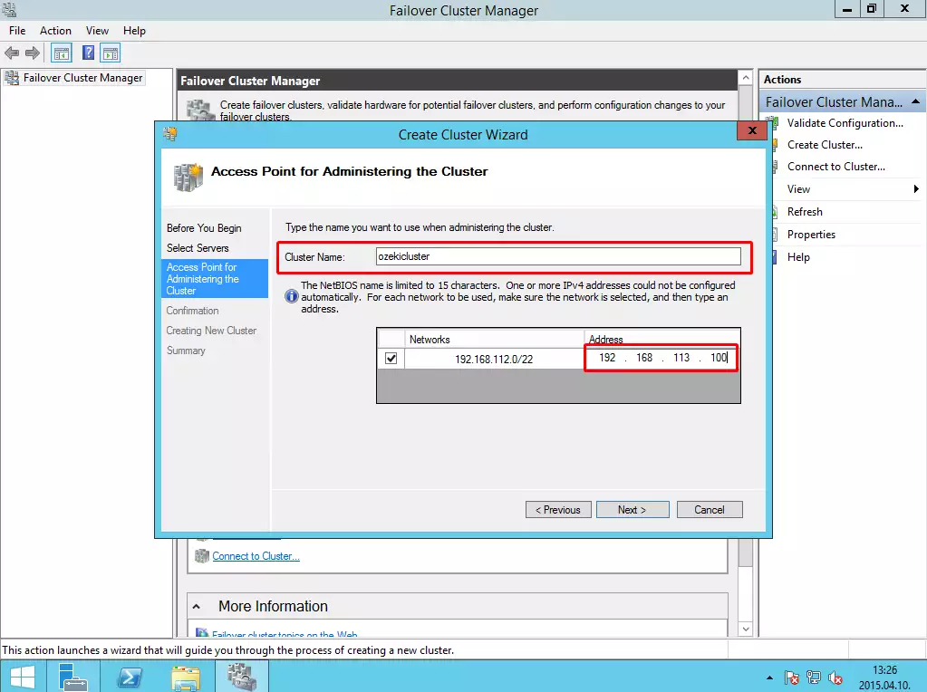
Provide a name and an IP address to the cluster.
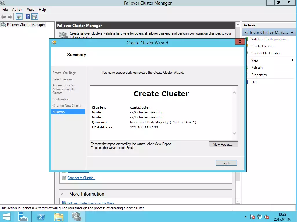
At the end of the installation, click on Finish button.
VIII. Adding Ozeki NG SMS Gateway to the cluster
After you have successfully created the cluster, you need to add Ozeki NG SMS Gateway and the shared storage as resources to the cluster.
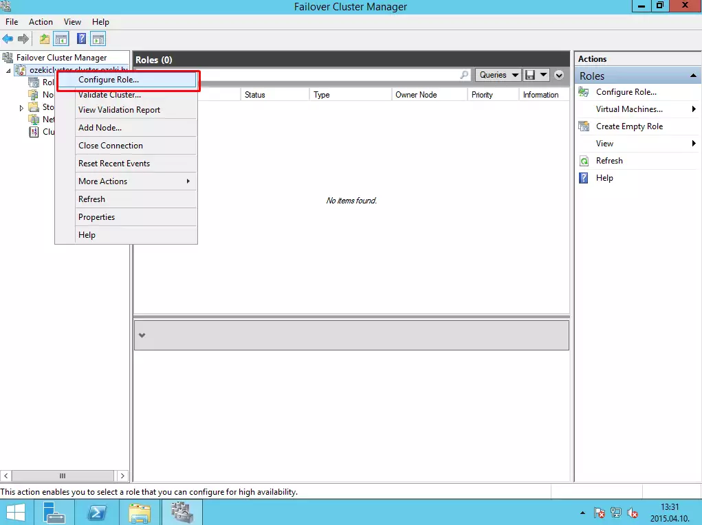
Right click on the name of the cluster, and click on Configure Role.
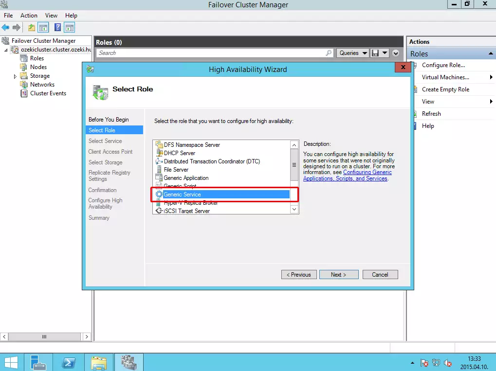
On the role list, select Generic Service and click on Next button.
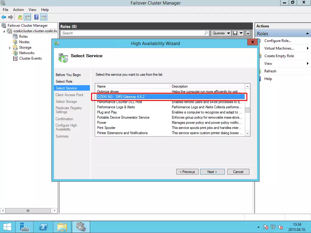
From the list of services, select Ozeki NG SMS Gateway.
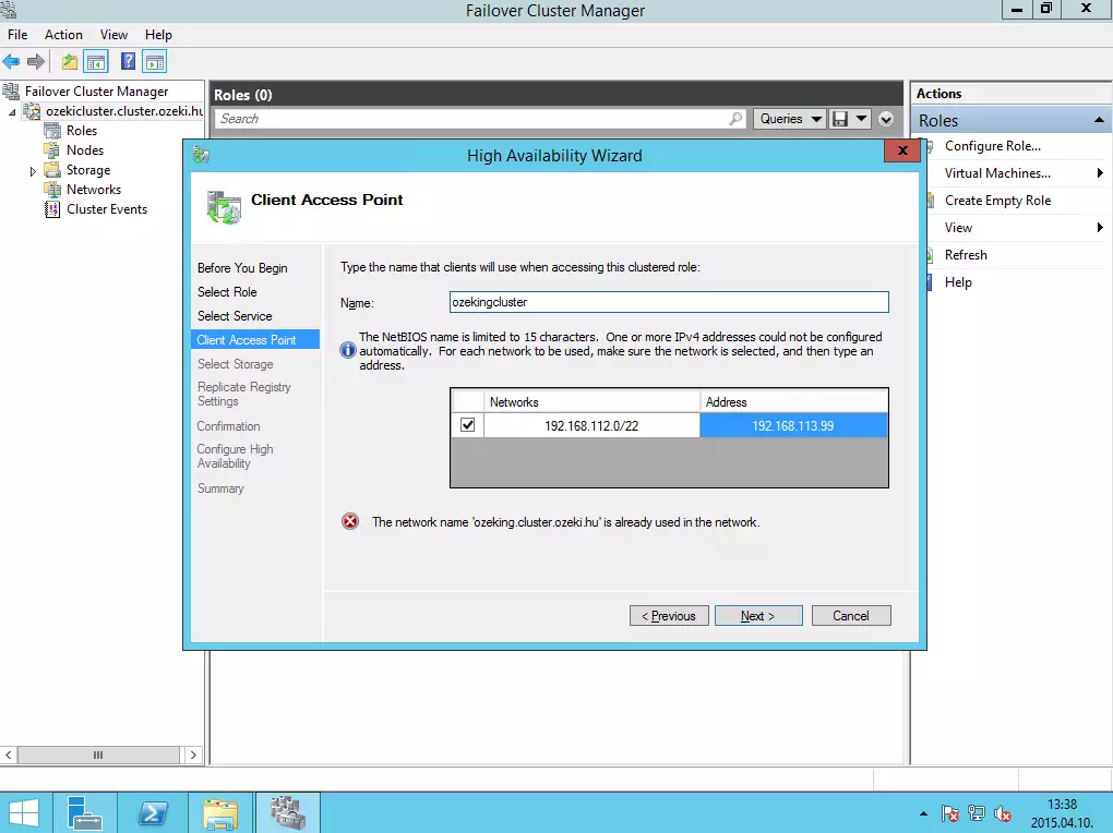
Then provide a name and IP address where users can access this role.
Then follow the steps, and always click on Next button without any modification.
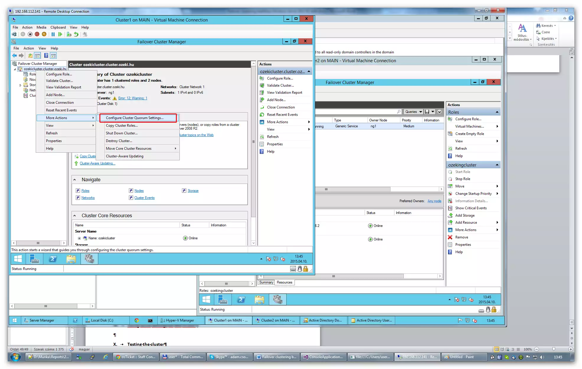
Now select Configure cluster quorum settings.
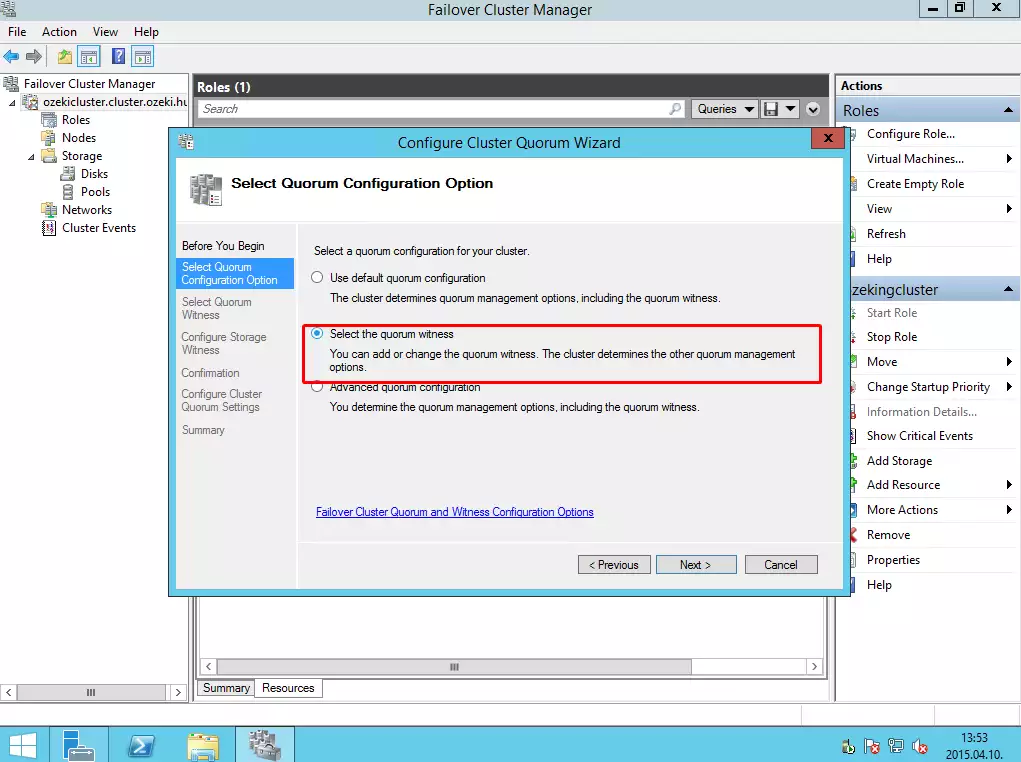
Select the Select quorum wittness.
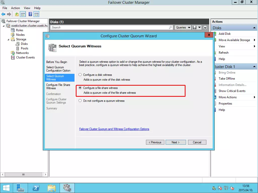
Then select Configure a file share wittness.
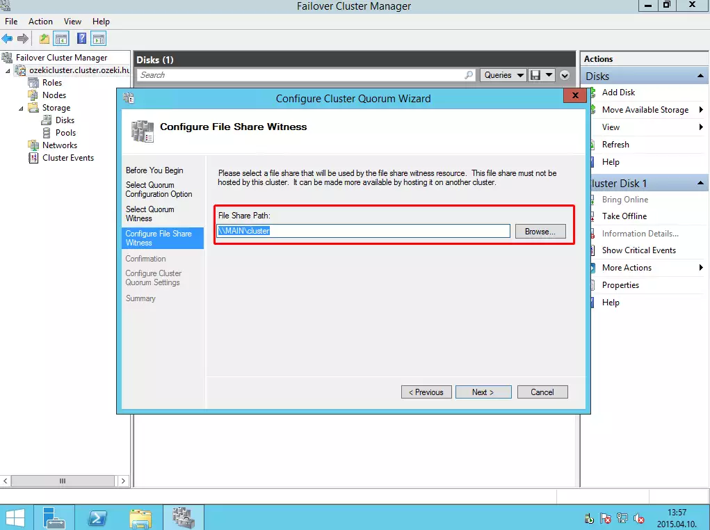
And finally provide a file share path to this cluster and follow the steps (just click on Next buttons).
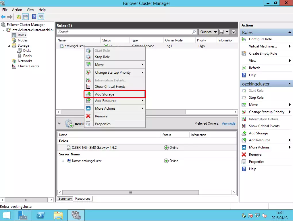
Then right click on the name of the role, and select Add storage button.
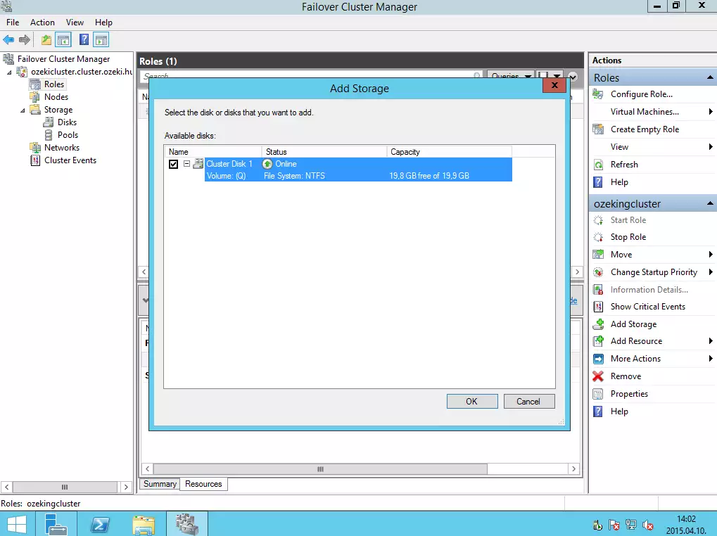
From the list, select the Q volume.
Then right click on the name of the Ozeki NG SMS Gateway service and click on Properties (here you can specify how many times the service can be restarted in the specified period).
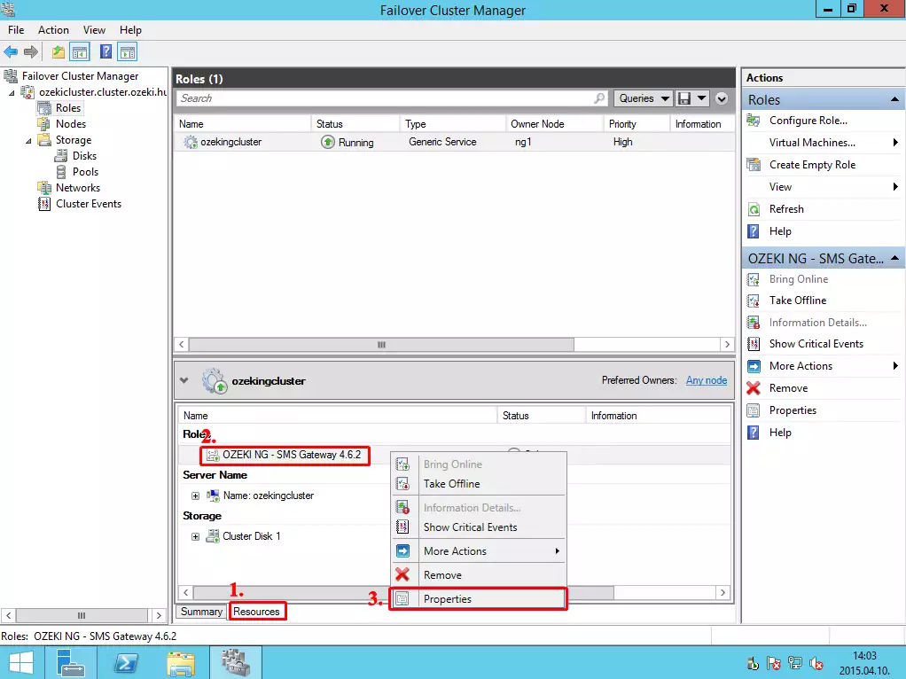
Under dependencies add a new dependency. This means that the service will be started when the shared disk will be online on the PC.
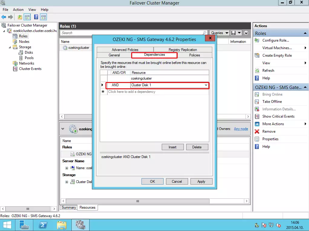
Under Policies tab, you can configure the maximum restart number in a specified period. In the Period for restarts and Maximum restarts in the specified period textboxes you need the specify the period in which the provided restart number will be allowed. In this example 10 restarts will be allowed in 15 minutes. After the next failure, the service will be restarted on the other node of the cluster.
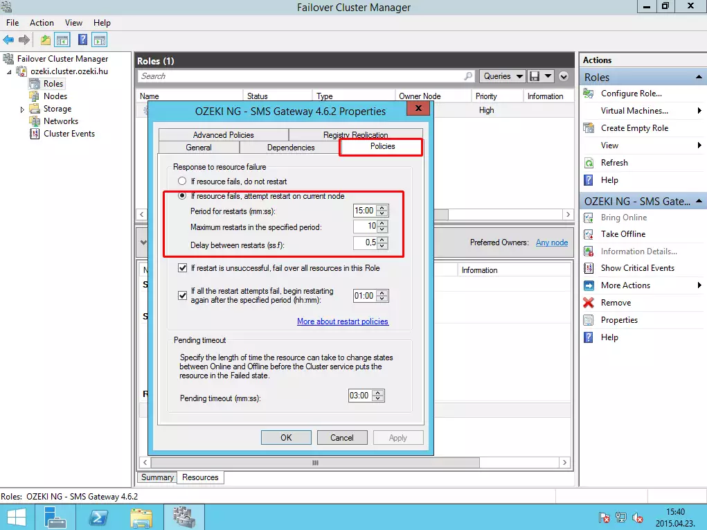
Now click with the right button on the name of the Role, and select Properties menu.
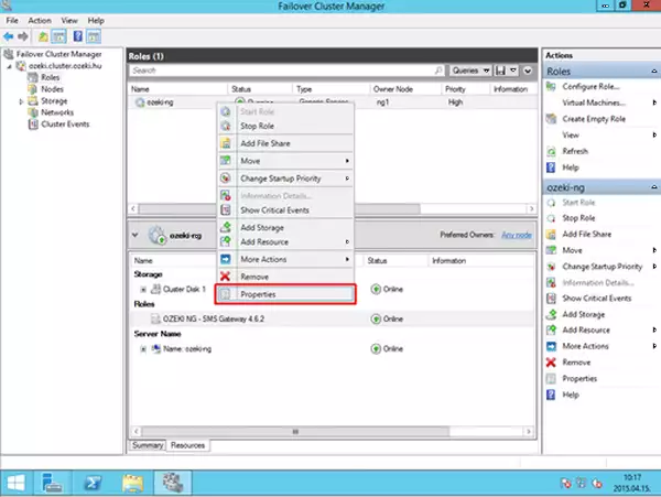
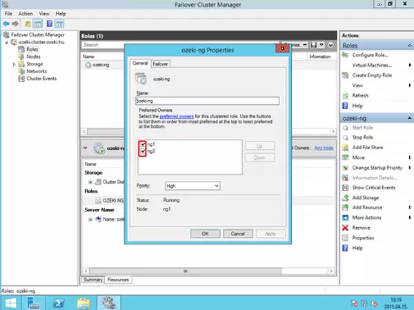
On the next window, under the General tab, select both nodes, and move to the top of the list the preferred node.
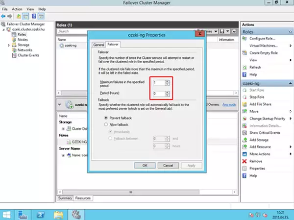
Under the Failover tab, configure the maximum failures in the specified period to 1 and the period (hours) to 0. This is not the same configuration that we have configured earlier.
IX. Testing the cluster
Now we have finished the configuration of the failover clustering. You can test the functionality in the following ways:
- If you shutdown the computer where Ozeki NG SMS Gateway is running, the other computer will take over the control over the service and the shared storage.
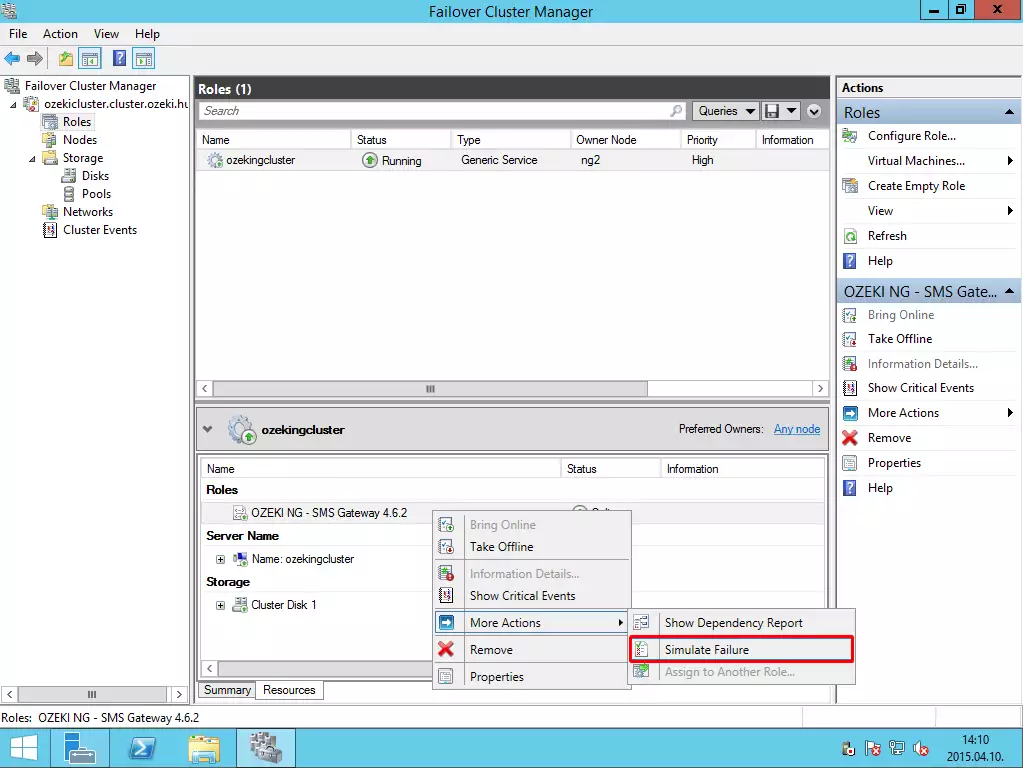
- Manually you can simulate failure by right clicking on the name of the service, select More actions and Simulate failures buttons.
If you have any other question, please send us an e-mail at info@ozekisms.com.
People who read this also read...
More information
